Articles
Chassis Manager Card, Instructions and Configuration

Overview:
1) General Description
2) Chassis Manager Card's Schematic
3) Chassis Manager Card's Components and Wiring
4) Configure CM Card Firmware
5) Compile and flash firmware through USB STK500V2 programmer
6) NITlab programmer
7) Sensors
1) Chassis Manager Card General Description
NITLAB designed and implemented a Chassis Manager(CM) card to control and monitor NITOS nodes. CM card is combined of a general purpose microcontroller, an ethernet microcontroller and a relay's circuit. The microcontroller can support a tiny WebServer, so it can communicate through network controller and http protocol with any other device in the same network. Exploiting this ability we can send http requests to CM card to give power to relays so they can bridge the jumbers of any motherboard to start/stop or reset their operation. Additionally CM card returns to us a http response and inform us about the operation status of the node.
Prototype Technical Information:
- Board kit: link
- AVR micro-controller ATmega328P
- Stand-Alone Ethernet Controller with SPI Interface ENC28J60
- Ethernet Magjack
- 2 reed relays
2) Chassis Manager Card Schematic
Relays Circuit Schematic:
This circuit is been implemented on the empty edge of CM card and is been connected with the microcontroller.
Microcontroller Circuit Schematic:

Here you can see the schematic in full quality.
3) Chassis Manager Card's Components and Wiring
CM card's connectors and components:

Connectors Polarity:

In order to connect and mount a CM card into a node you need to supply it with power.
For this reason you need to use this type of connector (scotchloks) :
You should connect it as it appears below:

In order to get power from the ATX power supply with the scotchloks, you should connect the positive connector to the purple cable and the negative connector to any black cable. As you can see on the image below the purple cable provides always +5v, even if the node is not shutted down.


*how this card will be connected with start/stop rest pins of ORBIT / COMMELL motherboars. insert images
4) Configure CM Card Firmware
In order to configure CM Card firmware you need to modify mac and ip addresses.
Download the firmware : link
Modify mac and ip addresses which are in the beggining of main.c file in the firmware folder.
static uint8_t mymac[6] = {0x54,0x55,0x58,0x10,0x00,0x1e};
static uint8_t myip[4] = {10,1,0,30};
Choose a unique mac address for your network and an ip address according to your network address.
5) Compile and flash firmware through USB stk500v2 programmer
First you should install avr library & avrdude on your computer:
sudo apt-get install avr-libc
sudo apt-get install avrdude
In order to compile cm card's firmware you need to give the command:
make
If you like you can delete any previous executable files by giving the command:
make clean
After compilation, you can flash the firmware in the CM card by giving the command:
avrdude -p m328p -c stk500v2 -e -U flash:w:eth_rem_dev_tcp.hex -P /dev/ttyUSB0
Hint: Please check at first the name of the port that is given at your programmer, by checking all available ports, with tab button after you have written /dev/ttyUSB in the console.
The stk500v2 programmer:

You should use crocodile cable to power CM card through stk500v2 programmer, in order to flash an image.
Be careful with the polarity of the programmer, you should put the connector on such way that the reset cable is been connected with the reset

*Insert some photos, about testing the cards after flashing an image by using a web browser.
In order to use our programmer you need to run the command:
avrdude -p m328p -c ponyser -e -U flash:w:eth_rem_dev_tcp.hex -P /dev/ttyS0
In order to send a http request, you need to use an Internet Browser such as Mozilla or console commands.
Browser:
Console commands:
curl http://10.1.0.1/
the last command just returns the status of each node.
6) NITlab programmer
Serial Programmer Developed for programming the AVR micro-controller:
- Electronic scheme (We used 3.3V zener diodes instead of 5.1V and 33K resistor instead of 15K)
- Photos 1, 2, 3
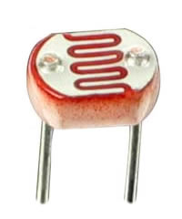
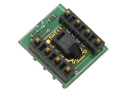
7) Sensors
Temperature & Humidity sensor:
Light sensor: