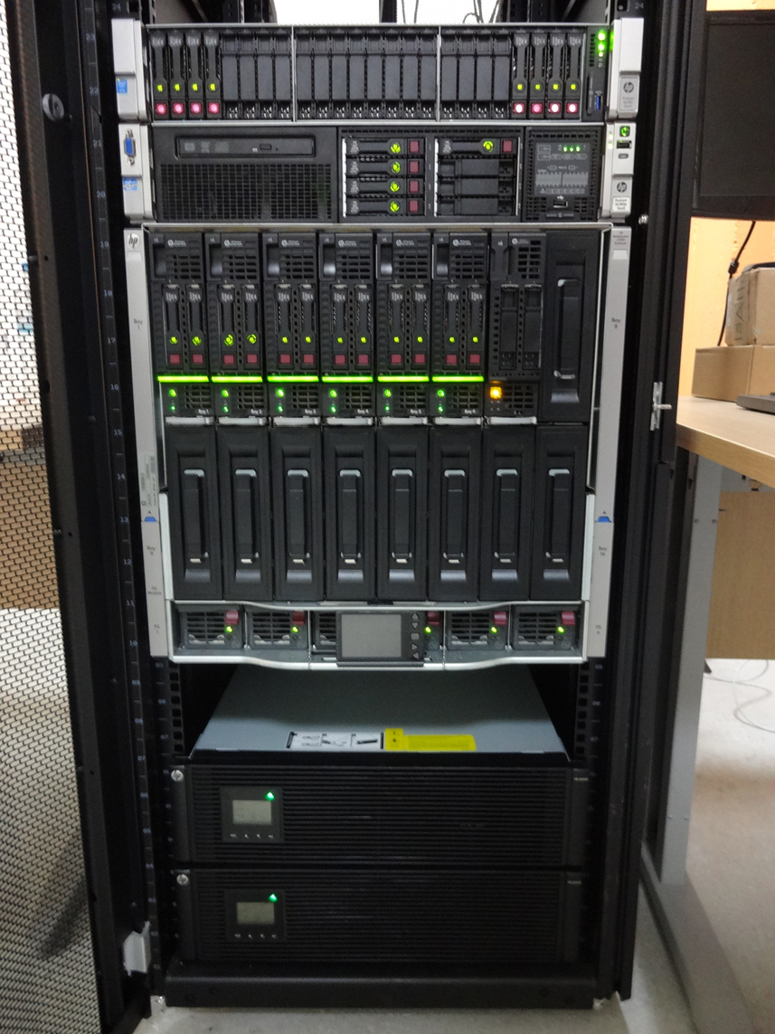
 Each blade server has
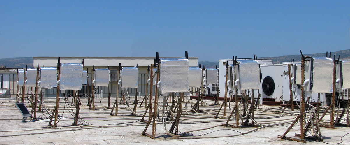
LoRa city-scale Testbed
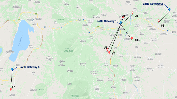
Testbed Topology
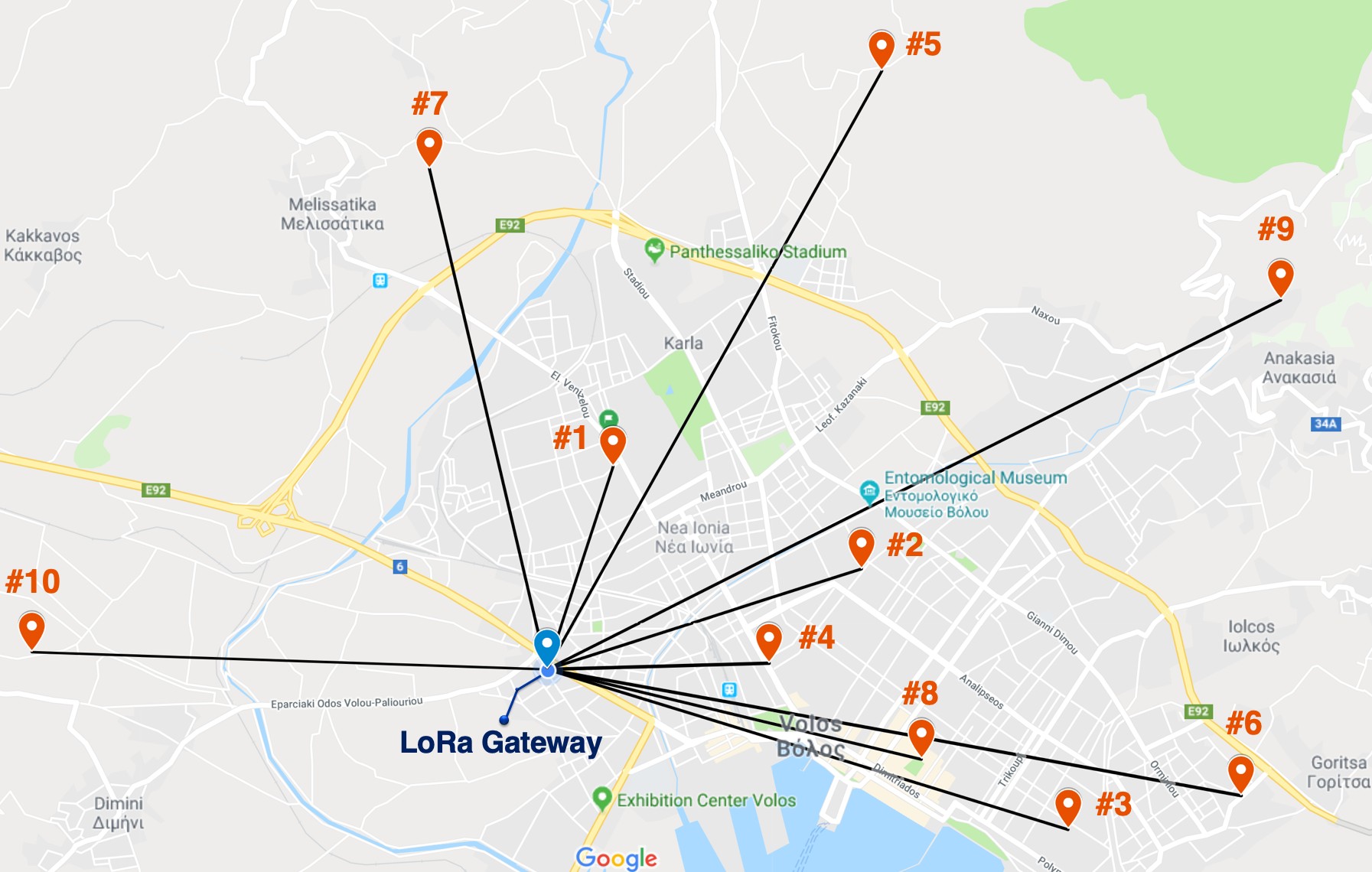
The LoRa testbed consists of one LoRa Gateway (GW ) that is deployed on the rooftop of our University’s premises and ten Sensing nodes that are scattered across the city of Volos, Greece. The end nodes feature various air quality probes, characterizing gas concentrations, dust particle con- centration, along with outdoor air temperature and humidity modules. We clearly observe that the testbed offers a wide range of wireless links that differentiate in terms of communication distance, elevation difference and LOS/NLOS conditions. For each node, we also note the amount of payload bytes transmitted when transferring the respective number of sensed parameters, which includes 5 Bytes per environ- mental parameter plus 9 Bytes of own protocol overhead, while it does not include the LoRa preamble, header and CRC, as specified in [5]. Below we present the custom developed GW and sensing devices, as well as the software toolkit for obtaining LoRa performance measurements.
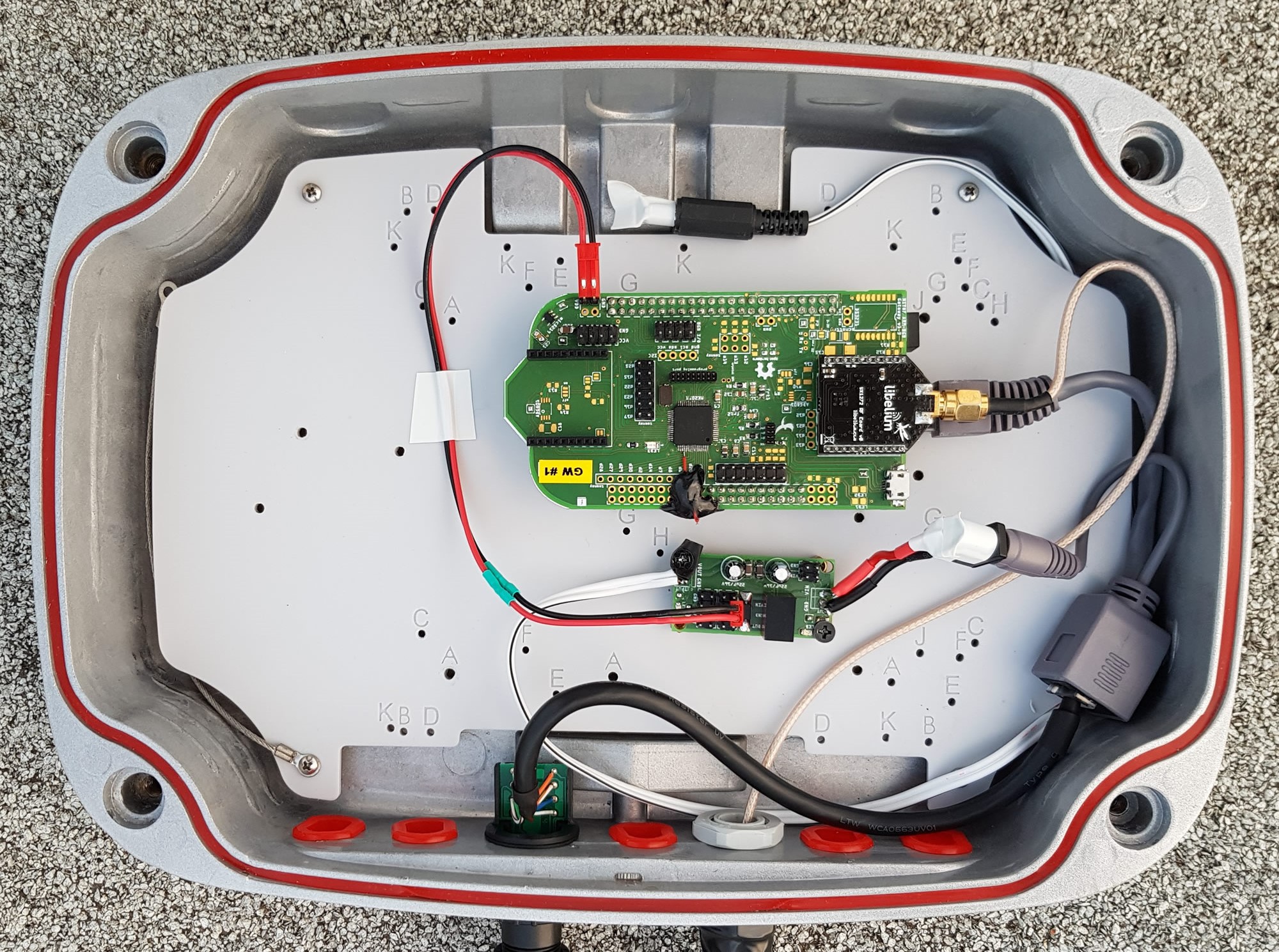
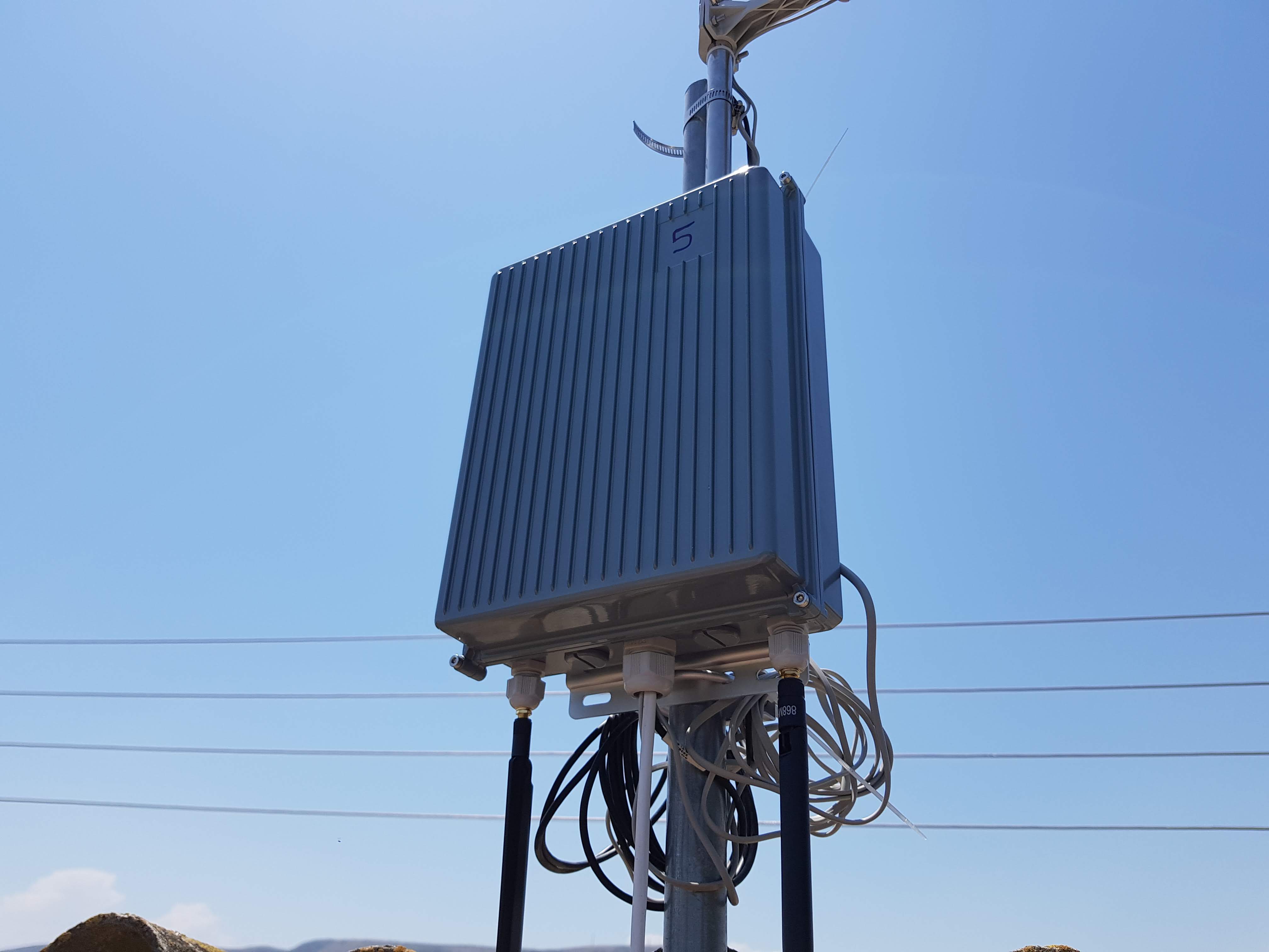
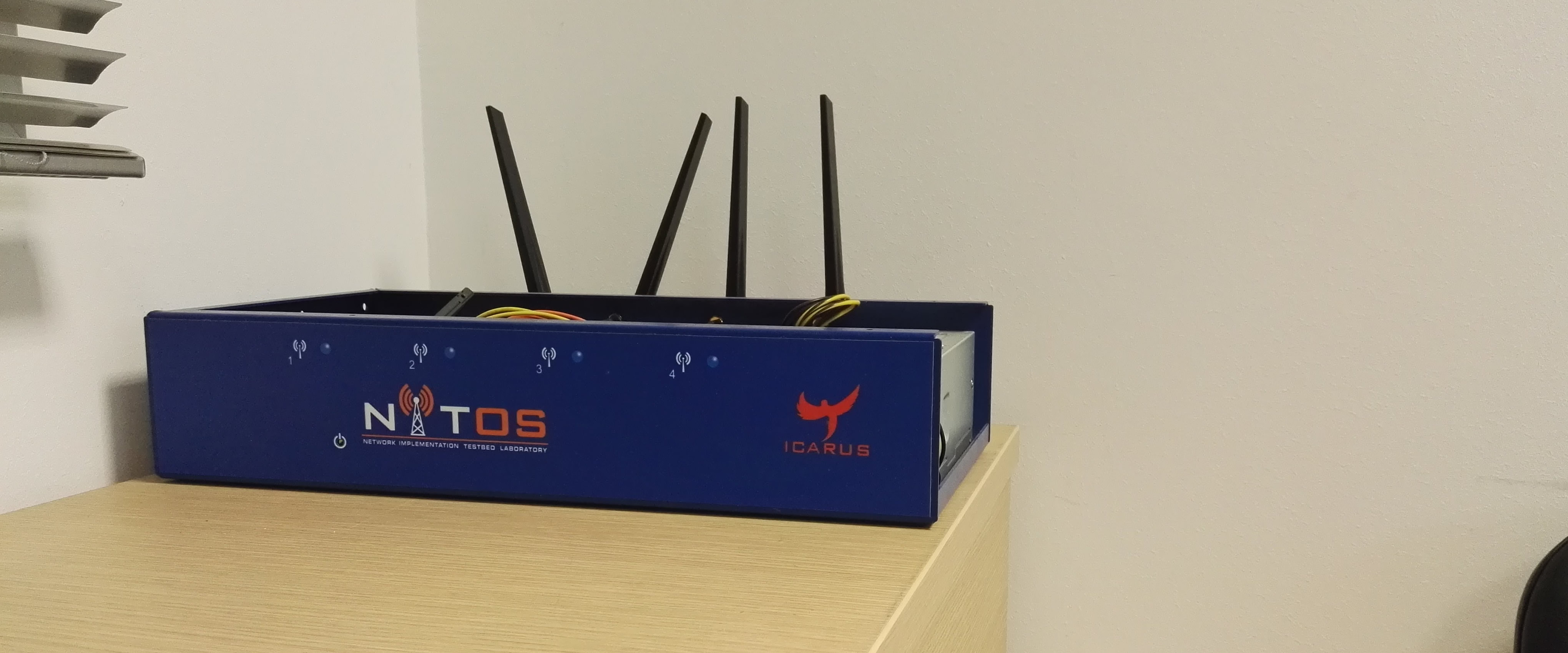
LoRa Gateway: The GW is based on the BeagleBone Black Rev. C board [18] which is a low-cost, embedded plat- form characterized by su cient processing power capabili- ties (ARM Cortex-A8 Processor at 1 GHz with 512 MB RAM) and several I/O pins, while it also embeds an Ethernet port for communicating with the backbone network. On top of BeagleBone we attach a custom-designed PCB board (cape) that integrates our electronic components and features a slot for connecting a LoRa transceiver. More speci cally, the cape features the MK20DX128VLH5 micro-processor which is interfaced with the LoRa transceiver responsible to run all the requisite libraries for its operation. The micro- processor software is also responsible of implementing a polling mechanism to aquire measurements from the sensor nodes and also initiate the link quality experiments. For the LoRa transceiver we employ the SX1272 [19] chipset manufactured by Semtech, which is paired with a 4.5 dBi antenna.
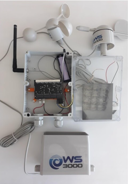
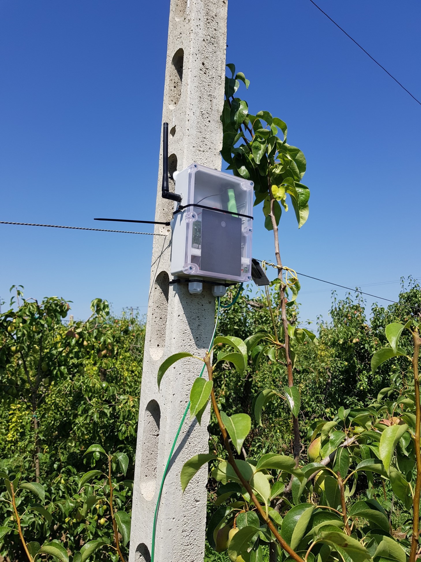
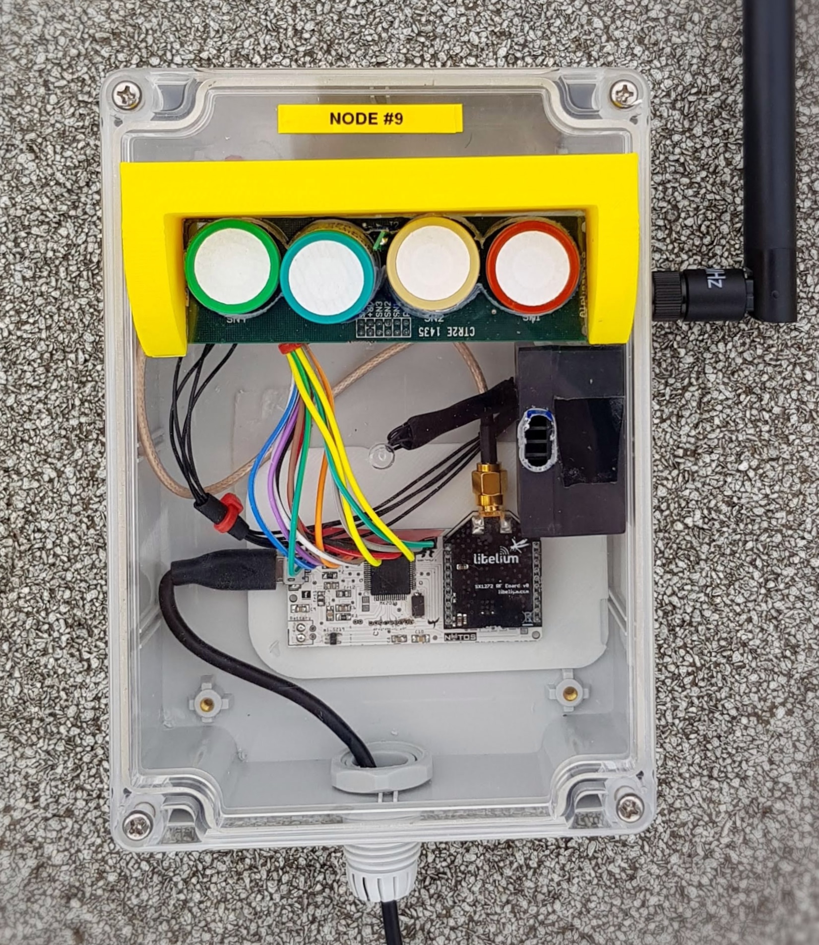
LoRa Sensing Devices: The core module of our sensing devices is again the MK20DX128VLH5 [20]. The 32-bit ARM Cortex-M4 CPU, clocks up to 96 MHz and supports ultra-low power sleeping modes to allow for power e cient opera- tions. The node employs the same LoRa interface (SX1272) as the gateway device, attached to a 4.5 dBi omni-directional antenna. Each node is equipped with a varying set of sensors, as illustrated in Table 1, featuring 1, 3 or 7 sensors in total. The sensors utilized are gas concentrations probes (NO2, SO2, CO, NH3, O3), dust particle concentration PM2.5, PM10 and a temperature & humidity module. The micro-processor hosts a program that implements the sensor reading and collec- tion of measurements, and also the communication between itself and the SX1272 module. Fig.1(b) presents one sensor device attached with four gas concentration probes and a dust particle module.
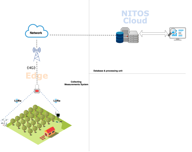
Software Toolkit: Through the deployed list of devices, we continuously collect detailed air quality measurements, while also evaluate the performance of the employed LoRa communication links. The overall procedure is orchestrated at the GW level, which periodically polls the di erent sens- ing nodes that continuously remain in receive mode. Sensor polling is executed in a Round-robin fashion, instructing sensors to transmit collected air quality measurements (with an interval of 10 minutes) or to participate in a link quality evaluation experiment (executed twice per day). The two procedures are executed independently of each other, taking advantage of the employed polling approach, which enables us to avoid the impact of overlapping transmission inter- ference, when performing link quality experiments. Upon receiving a request for experiment, each sensing node trans- mits 10 consecutive packets at the data rate, payload length and transmission power that has been determined by the GW. The gateway sends the experiment settings embedded to the experiment request packet. The per-node link quality of the network is determined through the Packet Delivery Ratio (PDR) of the aforementioned experiments.
Sensor Device