• 1
  • 2
  • 3
  • 4

Activities

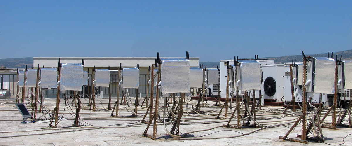
  • NITOS Outdoor deployment consists of powerful nodes that feature multiple wireless interfaces and allow for experimentation with heterogeneous (Wi-Fi, WiMAX,

    Read More
  • The setup NITOS testbed is currently using is a fixed setup (employing no mobility between BSs) that does not require

    Read More
  • Towards the development of a remote accessible LTE testbed, where experimenters from all the word will be able to run

    Read More
  • NITOS facility provides remote access to OpenFlow switches (2 x Pronto 3290 , 2 x HP 3800 ), enabling the user to create

    Read More
  • NITlab developed a software defined radio (SDR) testbed that consists of 18 Universal Software Radio Peripheral (USRP) devices attached to

    Read More
  • NITOS is an Intelligent Transport System (ITS) compatible facility thanks to the implementation of the key components of the ITS

    Read More
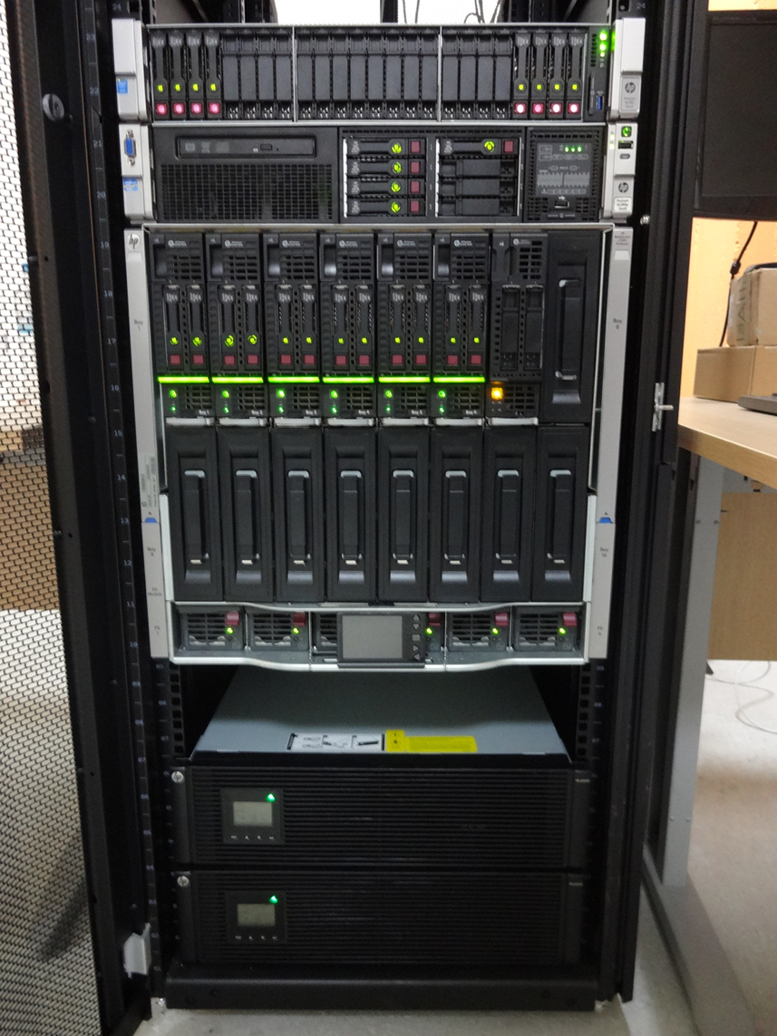
  • NITOS cloud infrastructure is based on HP GEN8 blade servers and one HP DL380p GEN8 server. Cloud Infrastructure UTH Each blade server has

    Read More

NITOS

The Future Internet Facility

  • Outdoor Testbed

    Experiments under real world environment Read More
  • Indoor Testbed

    Experiments in RF isolated environment Read More
  • Office testbed

    Experiments in an office environment Read More
  • 1
  • 2
  • 3

WiMAX tutorial

Using the WiMAX testbed

In order to use the WiMAX testbed resources offered by the NITOS facility, you will have to reserve the WiMAX base station and the nodes with WIMAX connectivity, offered by the testbed (nodes41-49).

Reserving the base station will render rights to the experimenter to access the WiMAXrf service of the testbed, used to configure and setup the base station at the experimenter's will.

After your reservation has started, login to the NITOS2 server with the following command:

 ssh This email address is being protected from spambots. You need JavaScript enabled to view it. 

Once you have logged in, you should setup the base station to the default settings, as its configuration might have been altered from its normal behavior by any previous experimenter. In order to setup the BS to the default settings you issue the following command:

 wget -qO- "http://wimaxrf:5054/wimaxrf/bs/default" 

Which will return you the message:

 BS is now set to its default parameters 

Since not all of the changes take place immediately, you will need to restart the base station for some of the changes to take effect. You can restart the BS with the following command:

 wget -qO- "http://wimaxrf:5054/wimaxrf/bs/restart" 

Which returns you the message:

 BS restarting 

It takes up to 5 minutes for the BS to be back operational. You can see the parameters that can be changed and the WiMAXRF service commands and their syntax by invoking the following command:

 wget -qO- "http://wimaxrf:5054/wimaxrf/" | xml_pp 

It returns an XML tree with the complete list of WiMAXRF commands. Since the BS is back to its default settings, you can start experimenting with the WiMAX testbed. In order to do so, you can login to your booked nodes with the command:

 ssh root@node0XX 

where XX is the number identifier of node reserved.

The WiMAX clients installed on the nodes are provided by Teltonika model UM6250. These devices are using a small linux client on them which is configured to serve the WiMAX network to the Linux OS as a simple Ethernet device.

Once you are logged on the node, you can see the WiMAX interface with an ifconfig command. The tel0 interface is the WiMAX device.

 tel0      Link encap:Ethernet  HWaddr 00:1e:42:02:1c:a4  
          inet6 addr: fe80::21e:42ff:fe02:1ca4/64 Scope:Link
          UP BROADCAST RUNNING MULTICAST  MTU:1500  Metric:1
          RX packets:103 errors:0 dropped:0 overruns:0 frame:0
          TX packets:139 errors:0 dropped:0 overruns:0 carrier:0
          collisions:0 txqueuelen:1000 
          RX bytes:7116 (7.1 KB)  TX bytes:9323 (9.3 KB)

There is an internal network on the 192.168.0.0/24 subnet that is used to operate with the Teltonika device. The device by default is using the 192.168.0.1 IP address. You can configure the tel0 device with an IP of this subnet and connect to the Teltonika device. eg.

 ifconfig tel0 192.168.0.46/24 up 

In order to connect the device to the NITOS BS, you can use the following commands:

wget --http-user admin --http-password admin -qO - "http://192.168.0.1/cgi/cli?stopSs"
wget --http-user admin --http-password admin -qO - "http://192.168.0.1/cgi/cli?addChannel frequency=2590000 bandwidth=10"
wget --http-user admin --http-password admin -qO - "http://192.168.0.1/cgi/cli?startSs"

These commands setup the USB dongle to communicate at a center frequency of 2590MHz with a 10MHz bandwidth. You can confirm that the dongle has connected to the BS with the following command:

wget --http-user admin --http-password admin -qO - "http://192.168.0.1/cgi/cli?showSs

Now you can connect to the Teltonika device with the command:

 telnet 192.168.0.1 700 

You can use as credentials:

 
username: admin
password: admin01

Once you are connected you can see the interfaces used by the client (eth0 and icc0).

eth0      Link encap:Ethernet  HWaddr 26:C7:FB:4F:47:C7  
          inet addr:192.168.0.1  Bcast:0.0.0.0  Mask:255.255.255.0
          UP BROADCAST RUNNING MULTICAST  MTU:1500  Metric:1
          RX packets:770 errors:0 dropped:0 overruns:0 frame:0
          TX packets:621 errors:0 dropped:0 overruns:0 carrier:0
          collisions:0 txqueuelen:1000 
          RX bytes:41041 (40.0 KiB)  TX bytes:65498 (63.9 KiB)

icc0      Link encap:Ethernet  HWaddr 00:1E:42:02:1C:A3  
          inet addr:192.168.55.46  Bcast:0.0.0.0  Mask:255.255.255.0
          UP BROADCAST RUNNING MULTICAST  MTU:1500  Metric:1
          RX packets:76451 errors:0 dropped:1 overruns:0 frame:0
          TX packets:46324 errors:0 dropped:0 overruns:0 carrier:0
          collisions:0 txqueuelen:1000 
          RX bytes:9143872 (8.7 MiB)  TX bytes:7121807 (6.7 MiB)

The icc0 interface is the WAN interface used to communicate with the BS. The default network that is served by the BS is the 192.168.55.0/24. You need to further add some rules to the dongle and the node in order to enable connectivity among the node's WiMAX interfaces with each other. In the dongle you have to add these rules:

 /bin/iptables -t nat -A PREROUTING -d 192.168.55.XX -j DNAT --to 192.168.0.YY

where XX is the node ID (eg. 46 for this example) and YY is the IP address of the tel0 interface. Finally, you have to add the appropriate routing rules to the node in order to be able to communicate over the WiMAX network. These rules are applied with the following commands:

route del default gw dev tel0
route add -net 192.168.55.0/24 gw 192.168.0.1 dev tel0

You can further check for statistics on the downlink quality of the WiMAX clients with the following command:

wget --http-user admin --http-password admin -qO - "http://192.168.0.1/cgi/cli?showPhyStatsRx

Orchestrating WiMAX experiments with OMF

The following is a sample experiment where the WiMAX interface is setup and we generate traffic between two nodes

defProperty('runtime',20,"Time in second for the experiment is to run")
defProperty('client',"192.168.55.48","IP address of iperf server")
defProperty('interval', "1", "Interval of Iperf measurements")
defProperty('sender', 'omf.nitos.node043', "ID of sender node")
defProperty('receiver', 'omf.nitos.node048', "ID of sender node")
 
defGroup('Sender', property.sender) do |node|
  node.net.t0.channel = "2590000,10"
  node.addApplication("test:app:iperf-5.4") do |app|
    app.setProperty('client', property.client)
    app.setProperty('interval', property.interval)
    app.setProperty('time', property.runtime)
app.setProperty('udp', true) app.measure('transfer', :samples =>1) end end defGroup('Receiver', property.receiver) do |node| node.net.t0.channel = "2590000,10" node.addApplication("test:app:iperf-5.4") do |app| app.setProperty('server', true) app.setProperty('interval', property.interval)
app.setProperty('udp', true) app.measure('transfer', :samples =>1) end end onEvent(:ALL_UP_AND_INSTALLED) do |event| wait 50 info "This is an iperf experiment using a teltonika modem" allGroups.startApplications wait property.runtime wait 2 allGroups.stopApplications wait 2 Experiment.done end

You can run it from the testbed server with the following command:

 omf exec experiment.rb --slice your_username 
NITOS - Planetlab Federation

1. The Scenario

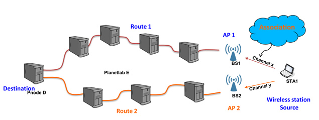
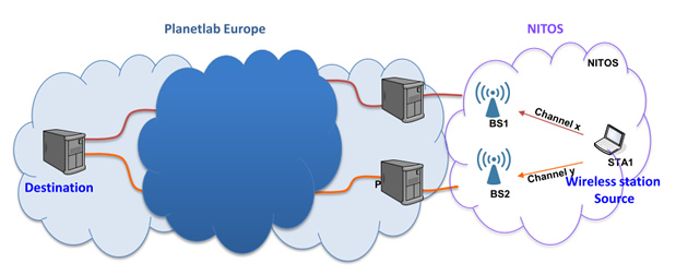
The experiment highlights the importance of association mechanisms in the general context of a network involving wired and wireless (Wi-Fi) components. The scenario is that of figure 1. A wireless station operating in an environment with two available access-points is sending traffic to a remote destination through the Internet. In current 802.11 WLANs, the station selects the AP to associate with only taking into account the RSSI values from the APs. This is clearly suboptimal even in an exclusively wireless context and much research work has focused on proposing new association metrics. The goal of this experiment is to shed light on an important parameter, often neglected in this context, the fact that the perceived QoS of a station depends on end-to-end performance metrics, rather than AP-specific metrics. In particular, one specific metric is taken into account, the end-to-end delay. However it is clear that extensions to more complex end-to-end metrics are relatively straightforward.

federation1

Figure 1: The scenario of our user association experiment


2. Resources involved

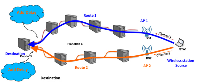
A synergy between two different testbeds is established for the purposes of the experiment, namely between the NITOS wireless testbed, located at the premises of the  University of Thessaly, and the large-scale distributed Planetlab Europe wired testbed. The University of Thessaly has two Planetlab nodes deployed at their facilities. These nodes are connected to two wireless nodes of NITOS, configured to operate as access-points. A third wireless NITOS node, in range with the former two, is used as the station sending the traffic. This traffic is destined to a remote Planetlab node, located at the INRIA facilities in Paris, France. The synergy between the two testbeds is depicted in Figure 2.


federation2

Figure 2: The synergy of NITOS and PLE during the experiment


3. Experiment Description

The three wireless nodes at NITOS are running modified versions of the MadWifi open-source driver. At the APs the drivers read a delay value from a specific proc-file. This value is obtained for each node through periodic pings to the destination node at INRIA taking place at the application level at regular time intervals. Each AP advertises this value through beacons, so that wireless stations in their neighborhood can take this parameter into account for their association decision. At the station side, the driver has been modified, so that the station associates to the AP with the lowest delay value, rather than to the AP with the highest RSSI. Again, it is clear that alternative policies using combined metrics of RSSI, delay and other parameters are straightforward to implement.

federation3

Figure 3: The actual scenario - Delay emulation through Dummynet


In order to control the delay of the different routes to the destination, a network emulator is being used on the destination side, Dummynet in particular. We configure Dummynet to apply different delays to the streams arriving from the two APs at NITOS and change this configuration periodically on the fly, as the experiment is running. The APs running the periodic ping applications sense these changes and update the relative proc-files accordingly.

Download the experiment description in OMF:

experiment.rb


4. Related paper

You can also download the relevant paper accepted in Tridentom 2012:

Keranidis_Federation_TridentCom_2012_paper.pdf


5. Demonstration through OMF

federation video

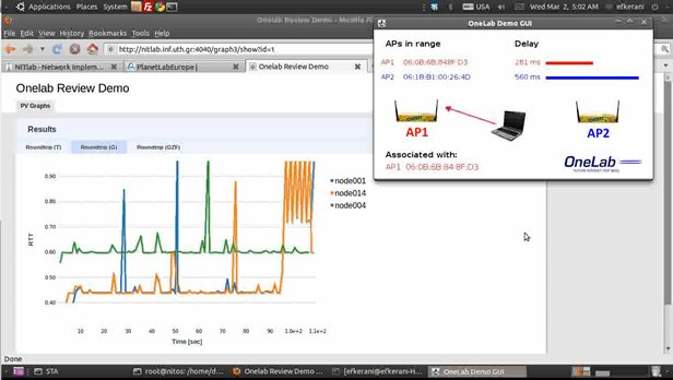
Figure 4: Screenshot from our Demonstration Video

The whole experiment is orchestrated through the OMF testbed control and management framework. NITOS has adopted OMF as its software framework and Planetlab nodes can incorporate OMF software upon request.

Capture Effect OMF/OML experiment

1. Scenario and topology


capture


In this scenario 3 nodes will be used:

  • 1 node will be the receiver
  • the other 2 nodes will be the senders

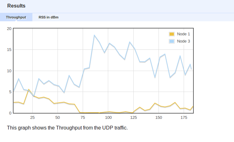
UDP traffic will be generated with iperf from the senders to the receiver. In the duration of the experiment we will decrease the transmit power of one node and notice how is affected the throughput.

The distance of the two nodes from the receiver is equal.


  • Both senders start sending traffic with 10Mbps and 20Mbps
  • Both senders have initial transmit power 17dBm
  • After the first 30 seconds the transmit power of the first node (10Mbps) is decreased to 14dBm
  • The transmit power of the first node is further reduced after 30 seconds (60th second) to 11dBm
  • At exactly the 120th second the transmit power of the first node is set back to its default value 17dBm.
  • The experiment is left to run 60 more seconds and then it is terminated.


2. Experiment Description in OMF

  1 #
2 # This application generates UDP traffic with iperf and simultaneously changes the transmission power of the senders.
3 # The measurement points collected, is the traffic generated from the UDP and the observed dBm values at the receiver
4 # The graphs depict firstly the throughput between the senders and the receiver and secondly the rssi values measured at the side of the receiver
5 #
6
7 defProperty('mode', 'a', 'The mode the nodes will be using')
8 defProperty('channel', '40', 'The wifi channel the nodes will be using')
9 defProperty('interval', 5, 'The interval in seconds between samples')
10 defProperty('duration', 180, 'The duration in seconds the iperf generates traffic')
11
12
13 # Define the applications and the interface settings of the Senders
14 defGroup('Sender1',"omf.nitos.node001"){|node|
15 node.addApplication("test:app:iperf") do |app|
16 app.setProperty('udp', true)
17 app.setProperty('client', '192.168.2.9') # define the ip of the receiver
18 app.setProperty('port', 5337)
19 app.setProperty('time',property.duration)
20 app.setProperty('bandwidth', 10000000) # 10 Mbps
21 app.measure('Peer_Info', :samples => 1)
22
23 end
24 node.net.w0.mode = "adhoc"
25 node.net.w0.type = property.mode
26 node.net.w0.channel = property.channel
27 node.net.w0.essid = "iperf_rssi_test"
28 node.net.w0.ip = "192.168.2.1"
29 }
30 defGroup('Sender2',"omf.nitos.node003"){|node|
31 node.addApplication("test:app:iperf") do |app|
32 app.setProperty('udp', true)
33 app.setProperty('client', '192.168.2.9') # define the ip of the receiver
34 app.setProperty('port', 5337)
35 app.setProperty('time',property.duration)
36 app.setProperty('bandwidth', 20000000) # 20 Mbps
37 app.measure('Peer_Info', :samples => 1)
38 end
39 node.net.w0.mode = "adhoc"
40 node.net.w0.type = property.mode
41 node.net.w0.channel = property.channel
42 node.net.w0.essid = "iperf_rssi_test"
43 node.net.w0.ip = "192.168.2.3"
44 }
45
46
47 # Define the applications and the interface settings of the Receiver
48 defGroup('Receiver',"omf.nitos.node009"){|node|
49 node.addApplication("test:app:iperf") do |app|
50 app.setProperty('udp', true)
51 app.setProperty('server', true)
52 app.setProperty('port', 5337)
53 app.setProperty('interval', property.interval) # interval in seconds between iperf reports
54 app.measure('UDP_Rich_Info', :samples => 1)
55 app.measure('Peer_Info', :samples => 1) # interval between collected iperf reports
56 end
57 node.addApplication("wlanmonitor_app") do |app|
58 app.setProperty('interface', 'ath0')
59 app.setProperty('sampling', 1)
60 app.measure('wlanstat')
61 end
62 node.net.w0.mode = "adhoc"
63 node.net.w0.type = property.mode
64 node.net.w0.channel = property.channel
65 node.net.w0.essid = "iperf_rssi_test"
66 node.net.w0.ip = "192.168.2.9"
67 }
68
69 onEvent(:ALL_UP_AND_INSTALLED) {|event|
70 wait 15
71 group("Receiver").startApplications
72 wait 1
73
74 group("Sender1").startApplications
75 group("Sender2").startApplications
76 wait 30
77 info("Changing Transmission Power to 14dBm")
78 group("Sender1").exec("iwconfig ath0 txpower 14")
79
80 wait 30
81 info("Changing Transmission Power to 11dBm")
82 group("Sender1").exec("iwconfig ath0 txpower 11")
83
84 wait 60
85 info("Changing Transmission Power to 17dBm")
86 group("Sender1").exec("iwconfig ath0 txpower 17")
87 wait 60
88 allGroups.stopApplications
89 wait 600 # for evaluation of the graph
90 Experiment.done
91 }
92
93 # Define a graph to display while the experiment is running
94
95 addTab(:defaults)
96 addTab(:graph2) do |tab|
97 opts = { :postfix => %{This graph shows the Throughput from the UDP traffic.}, :updateEvery => 1 }
98 tab.addGraph("Throughput", opts) do |g|
99 data = Hash.new
100 stations = Hash.new #keeps track the Node's number via the ID of the iperf connection
101 mp = ms('UDP_Rich_Info') #This measurement point contains all the iperf reports
102 mp2 = ms('iperf_Peer_Info') #This measurement point contains the IDs of the peers
103 # access the measurements of the 'iperf_Peer_Info'
104 mp2.project(:ID, :foreign_address).each do |sample|
105 id, address = sample.tuple
106 stations[id] = address.split('.').last #we keep track of the last number of the ip. By convention tha last part of the ip corresponds to the number of the node
107 end
108
109 #access the measurements of the 'UDP_Rich_Info'
110 mp.project(:oml_ts_server, :ID, :Bandwidth).each do |sample|
111
112 time, id, bw = sample.tuple
113
114
115 data[stations[id]]=[] if data[stations[id]]==nil # initialization of the data[] array
116 bw = bw * 8 / 2**20 #Mbps ( bytes * 8 / 2^20 )
117 data[stations[id]] << [time, bw] # stations[id] gives us the correct number of the node
118 end
119 data = data.sort # ascending order of the array. [ 1 2 3 ...]
120 data.each do |k,v|
121 g.addLine(v, :label => "Node #{k}") # we depict the bandwidth of each node. data[1] corresponds to BW value of Node 1...data[2]... etc
122 end
123 end
124
125 #Graph with the rssi values
126
127
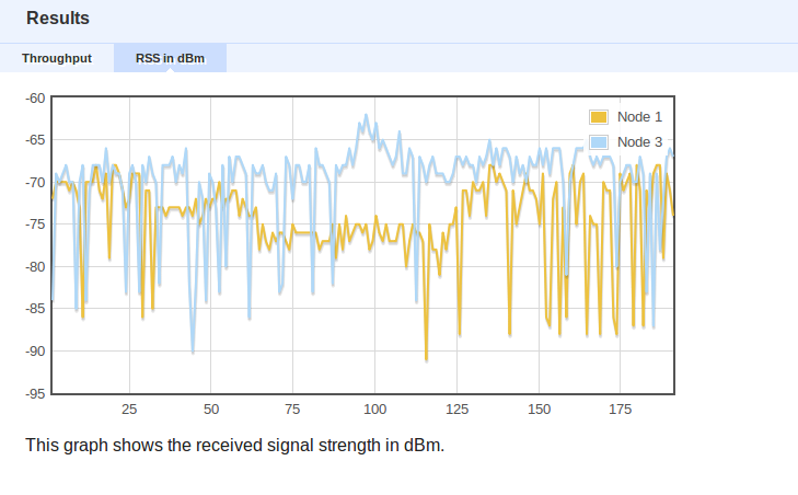
128 opts = { :postfix => %{This graph shows the received signal strength in dBm.}, :updateEvery => 1 }
129 tab.addGraph("RSS in dBm", opts) do |g|
130 data = Hash.new
131 # we keep track of the MACs of our nodes, in order to use more familiar names like "Node X" instead of the MAC address
132 nodes = {
133 "06:1b:b1:00:26:62" => "Node 1",
134 "06:1b:b1:00:26:6f" => "Node 2",
135 "06:1b:b1:00:26:b0" => "Node 3",
136 "06:1b:b1:00:26:bb" => "Node 4",
137 "06:0b:6b:84:8f:d3" => "Node 4", # ath1 interface
138 "06:1b:b1:00:26:85" => "Node 5",
139 "06:1b:b1:00:26:b4" => "Node 6",
140 "06:1b:b1:00:26:a8" => "Node 7",
141 #"06:1b:b1:00:26:5e" => "Node 9",# we comment out Node 9 in order not to measure it's own rssi values in the graph
142 "06:1b:b1:00:26:4d" => "Node 14",
143 "06:1b:b1:00:26:70" => "Node 15"
144 }
145 # Measurement point of wlanconfig
146 mp = ms('wlanstat')
147 mp.project(:oml_ts_server, :src_addr, :dbm).each do |sample|
148 time, src, dbm = sample.tuple
149
150 #we don't show in the graph rssi values from Nodes that do not belong to our setup
151 next unless nodes.has_key?(src)
152
153 data[nodes[src]] = [] if data[nodes[src]] == nil # initilization of the data
154 data[nodes[src]] << [time, dbm] # data will have the following format: data["Node X"] = [time, rssi_value]
155 end
156 data = data.sort # ascending order... Node 1...Node 2... etc
157 data.each do |d,v|
158 g.addLine(v, :label => d)
159 end
160 end
161 end


3. Running the experiment and viewing the results.

To run the above experiment simple type in the console the following command.

omf exec iperf_power_rssi.rb

where iperf_power_rssi.rb is the name of the file that has the experiment description.

Then we go to the following address to see our graphs

http://nitlab.inf.uth.gr:4000

Here are some screenshots from the results of the experiment

screenshot1

screenshot2

Video Link:

http://www.youtube.com/watch?v=KZIfpz43Ww4

What Our Experimenters Say

  • NITOS is a very reliable and well managed platform. The offered infrastructure and features are great. The management team is very supportive.

    Mustafa Al-Bado
    Postdoctoral researcher
    Insight centre, University College Cork (UCC)
  • 1
  • 2
 
uth
image
image
image


Login Form